

Our News
Find out about our latest news here.
Latest News
- ▶ Why Radiography Often Fails on Spiral Plate Heat Exchanger Shells — and How Phased Array UT Solves It
- ▶ EAC Certification for Chinese Pressure Vessels: What It Takes to Export Under TR CU 032/2013
- ▶ Spiral Plate vs Shell and Tube Heat Exchanger: Which One Fits Your Duty?
- ▶ CDQ Waste Heat Boilers: What Governs the Design, and What Actually Breaks
- ▶ What Are the Heating Surfaces in a Waste Heat Boiler? Superheater, Evaporator and Economizer Explained
- ▶ Buying Pressure Vessels from China: How to Read a Q345R and an SA-516 Gr.70 Mill Certificate
Message
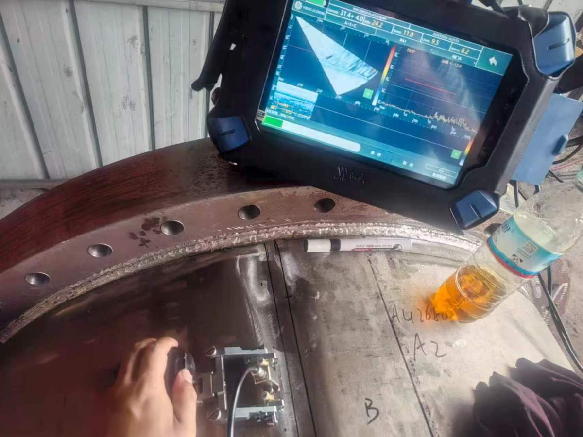
Spiral plate heat exchangers earn their place in refineries and chemical plants for good reasons: a single long channel per fluid, high turbulence, strong resistance to fouling, and a compact footprint. They are a natural choice for dirty or viscous services such as crude overhead condensing, slurry heating and heat recovery from process residues.
But the same geometry that makes them efficient creates a real headache for quality control. When a specification calls for full volumetric examination of the shell welds, the default answer — radiography — frequently turns out to be impractical or outright impossible.
This article explains why, what the ASME Code permits as an alternative, and how we use encoded phased array ultrasonic testing (PAUT) to examine these welds with full coverage and a permanent data record.
The problem: there is no "other side" to put the film
Radiographic testing (RT), whether film or digital (DR), needs two things: a radiation source on one side of the weld and a film or detector on the other.
On a conventional pressure vessel, that is straightforward. On a spiral plate exchanger, the space directly behind the shell wall is not open — it is the spiral channel itself, formed by plates wound tightly around a central core with a gap of only a few millimetres to a few centimetres. There is no way to place a detector inside.
The usual workaround, a double-wall exposure from the outside, does not help much either. The radiation beam would have to pass through multiple wraps of spiral plate before reaching the far wall, producing an image with layers of superimposed metal that cannot be reliably interpreted. Add the typical diameter and wall thickness of these units, and the exposure geometry simply does not meet the image quality requirements of ASME Section V.
In short: specifying "100% RT" on a spiral plate shell seam often specifies something the physical construction does not allow.
What ASME Section VIII, Division 1 allows
The ASME Code recognised this kind of limitation long ago. Ultrasonic examination in lieu of radiography was first permitted through Code Case 2235 in 1996, and the rules have since been incorporated into the Code itself.
Today, UW-51(a)(4) of Section VIII, Division 1 permits UT in place of RT for welds in material 6 mm (1/4 in.) and thicker, provided the examination meets the requirements of Section VIII, Division 2, paragraph 7.5.5. Key conditions include:
• Computerised, encoded data acquisition. Manual UT is not accepted as the primary technique. The equipment must record position-encoded data so that the full weld volume can be imaged and reviewed later — which is exactly what PAUT and TOFD provide.
• A written, demonstrated procedure following Section V, Article 4, including its mandatory appendices for computerised imaging techniques.
• Qualified personnel for data acquisition and analysis.
• Fracture-mechanics-based or workmanship acceptance criteria as defined by the Code.
Importantly, a weld examined by UT under these rules receives the same credit as radiography when determining the weld joint efficiency under UW-12. The design does not lose anything by switching methods.
Why PAUT is the right tool for this job
Phased array UT uses a probe containing many small elements that can be fired with precise time delays. This steers and focuses the ultrasonic beam electronically, sweeping it across a range of angles in a single pass — a sectorial scan (S-scan).
For spiral plate shell welds, this brings several practical advantages:
• Single-side access. All scanning is done from the outer surface of the shell. Nothing needs to be placed inside the unit.
• Full volumetric coverage. A sectorial sweep, combined with scanning from both sides of the weld where possible, covers the weld metal and heat-affected zone from root to cap.
• Better detection of planar flaws. Lack of fusion and cracks — the most dangerous defect types — are oriented in ways that RT can miss but UT reflects strongly.
• Depth and height sizing. PAUT reports not just where an indication is along the weld, but how deep it sits and how tall it is. That is what fracture-mechanics acceptance criteria require.
• A permanent, auditable record. With an encoder on the scanner, every millimetre of weld is recorded. Inspectors, clients and third parties can re-analyse the raw data at any time.
• No radiation. No exclusion zones, no night shifts, no interruption to other shop work.
The extra challenge: austenitic and super-austenitic stainless steels
Many spiral plate exchangers are built from high-alloy stainless steels such as 316L, 317L or 904L for corrosion resistance. These materials make ultrasonic testing harder.
Austenitic weld metal solidifies with coarse, columnar grains that are acoustically anisotropic. Sound travelling through them scatters, loses energy and can bend away from its intended path. The result is higher background noise and a risk of mispositioning indications.
We address this by:
• Selecting probe frequency and wedge angles suited to coarse-grained austenitic welds, balancing penetration against resolution.
• Building calibration and reference blocks from the same material grade and, where possible, the same welding procedure as the production weld, so that sensitivity is set under realistic conditions.
• Verifying the setup against known reference reflectors before production scanning, confirming that the sectorial scan actually reaches every part of the weld volume.
• Using encoded line scanning so that analysis is done on the complete dataset rather than on a technician's live judgement at the probe.
Choosing the right method for each joint
PAUT is not a replacement for radiography everywhere. We operate in-house digital radiography as well, and for joints with good two-sided access — nozzles, channel welds, standard shell seams on conventional vessels — RT or DR remains an efficient, well-understood choice.
The point is to match the method to the geometry. For spiral plate exchangers, where the construction itself rules out a detector position, PAUT is the method that actually delivers the examination the specification intends.
A checklist for buyers and EPC engineers
If you are specifying or reviewing a spiral plate heat exchanger, these questions will save time later:
1. Is RT physically possible on every weld you have specified it for? If not, agree on UT in lieu of RT at the bid stage rather than after fabrication starts.
2. Does the NDE plan reference UW-51(a)(4) and Section VIII Div. 2, 7.5.5? This confirms the joint efficiency basis is preserved.
3. Will the manufacturer provide the encoded raw data files, scan plans and procedure qualification — not just a summary report?
4. How will the manufacturer handle austenitic weld metal? Ask about calibration blocks and probe selection.
5. Who reviews the data? Confirm your third-party inspector or AI is comfortable reviewing PAUT results.
Talk to us
Boyu designs and fabricates spiral plate and shell-and-tube heat exchangers and pressure vessels under ASME U stamp certification, with in-house PAUT and digital radiography. If you have a project where the specified NDE does not fit the equipment geometry, send us the drawings — we will propose an examination plan that meets the Code and your specification.
PROFESSIONAL CONSULTATION
If you are interested in our products and want to know more details, please leave a message here, we will reply you as soon as we can.