


HRSG Heating Surface Design: Tube Materials, Fin Geometry and Manufacturing Practice
A practical framework for selecting and manufacturing HRSG heating surfaces along the gas-temperature profile.
Summary
HRSG heating-surface design is not a matter of applying one tube grade or one fin configuration throughout the unit. The appropriate solution changes along the gas path and should be verified against the actual project design basis.
1. Why HRSG Heating Surfaces Use Finned Tubes
A heat recovery steam generator is predominantly a convective heat exchanger. Gas-turbine exhaust transfers heat across tube banks to water or steam flowing inside the tubes.
On the gas side, the heat-transfer coefficient is normally much lower than on the water or boiling side. Extended surface is therefore widely used to obtain the required duty within a practical module size and gas-path depth.
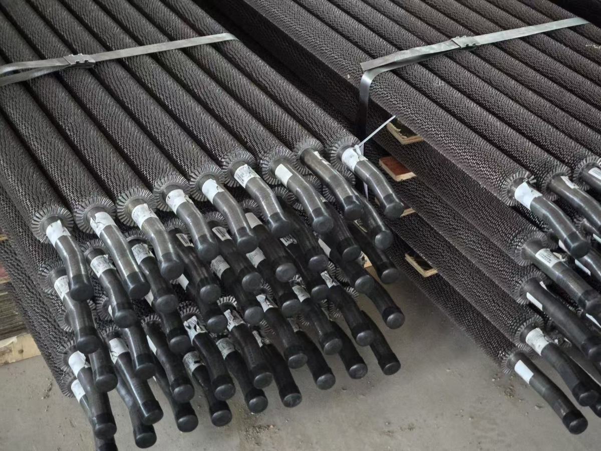
A common HRSG construction is the high-frequency resistance-welded (HFW) helical finned tube. A fin strip is continuously wound onto the tube while localized high-frequency resistance heating and pressure form a welded bond between the fin and tube.
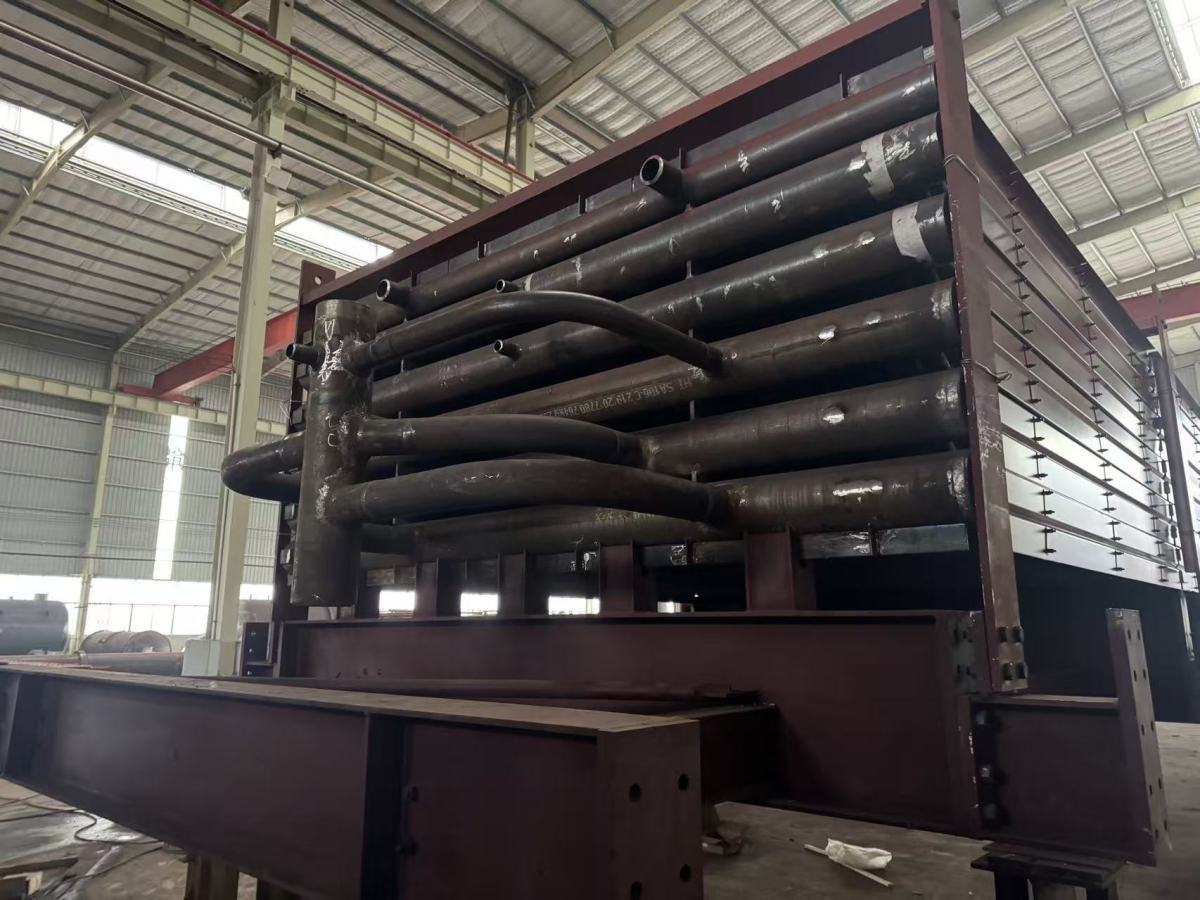
The finned tubes are then fabricated into:
- straight tube-bank elements;
- serpentine coils;
- header-connected heating-surface assemblies; and
- transportable HRSG modules.
The final arrangement depends on thermal duty, allowable pressure drop, module dimensions, lifting and shipping limitations, maintenance access and project-specific structural requirements.
Surface area alone is not a performance guarantee
A larger external surface area does not automatically mean a better HRSG design.
Changing fin height, pitch, thickness or type changes:
- effective heat-transfer coefficient;
- fin efficiency;
- gas velocity through the bundle;
- pressure drop;
- tube-metal temperature;
- fouling behaviour; and
- cleaning accessibility.
For technical comparison, guaranteed thermal duty, gas-side pressure drop, outlet conditions and the complete finned-tube geometry are more meaningful than surface area alone.
2. The Gas-Temperature Profile Defines the Design Zones
The starting point for heating-surface selection is the project-specific exhaust-gas condition supplied by the gas-turbine OEM or process designer.
A typical multi-pressure HRSG may arrange heating surfaces along the gas path approximately as follows:
GT exhaust / hot gas
    ↓
HP Superheater / Reheater
HP Evaporator
HP Economizer
IP Superheater
IP Evaporator / Economizer
LP Superheater
LP Evaporator
LP Economizer / Condensate Preheater
    ↓
Stack
The exact sequence varies with cycle arrangement, steam parameters, supplementary firing, SCR/CO catalyst arrangement and project configuration.
The important design point is that gas temperature changes continuously through the HRSG. The heating surfaces at the hot end and cold end therefore do not face the same material, corrosion or fin-temperature conditions.
For this reason, a well-designed HRSG normally grades the following along the gas path:
- tube material;
- fin material;
- fin height;
- fin pitch / fin density;
- solid or serrated fin configuration;
- tube spacing;
- row arrangement; and
- cleaning provisions where required.
Project-specific OEM exhaust temperature, mass flow, pressure-drop allowance and operating cases should always be used as the design basis.
3. Base-Tube Material Selection
Base-tube material should be selected from the calculated design metal temperature, pressure, applicable construction Code and required material properties.
Gas temperature alone is not a sufficient basis for selecting the pressure-part material.
3.1 Typical material families
The following grades are commonly encountered in HRSG and waste-heat boiler heating surfaces. Their actual use must be confirmed against the applicable Code and calculated design conditions.
Chinese GB grades or other national grades should not be treated as direct equivalents solely by nominal chemistry. Material substitution requires review of the applicable standard, allowable stress, heat treatment, dimensions, mechanical properties, welding requirements and project approval.
3.2 Hot-end selection: use calculated metal temperature
For superheaters and reheaters, the tube wall operates above the internal steam temperature because heat must pass through the gas film, fin, tube wall and internal steam-side film.
The required tube grade therefore depends on factors including:
- steam temperature and pressure;
- local gas temperature;
- gas-side and steam-side heat-transfer coefficients;
- tube diameter and wall thickness;
- fin geometry;
- tube spacing and row position; and
- design margin required by the applicable Code.
This is why the hottest gas row does not automatically require the highest alloy grade, and why the same tube material should not be assumed suitable throughout the entire superheater or reheater.
3.3 Grade 91 requires additional fabrication control
Where SA-213 T91 or other high-alloy ferritic/martensitic materials are used, fabrication control becomes more demanding.
Important controls include:
- material identification;
- qualified welding procedures;
- preheat and interpass-temperature control;
- controlled heat input;
- post-weld heat treatment where required;
- hardness verification where specified; and
- careful management of dissimilar-metal transitions.
Grade 91 weldments also require attention to long-term creep behaviour, including the potential for Type IV damage in the heat-affected zone under high-temperature service.
Material selection should therefore consider not only allowable stress, but also whether the fabrication and quality-control route can reliably support the selected grade.
3.4 Cold-end selection: corrosion can govern before strength does
At the cold end of an HRSG, material strength is often not the main concern. Fuel composition, water/steam temperature and the possibility of acid or water dew-point corrosion can become more important.
The cold-end design may therefore require review of:
- minimum tube-metal temperature;
- fuel sulphur and contaminant content;
- expected operating and start-up conditions;
- feedwater-temperature control;
- recirculation strategy;
- fin pitch and fouling tendency; and
- corrosion-resistant materials or coatings where justified.
Dual-fuel or process-gas applications should be checked against the most corrosive credible operating case, not only the normal clean-fuel condition.
3.5 Cycling duty affects both materials and structure
HRSGs that start and stop frequently experience repeated temperature transients.
These transients can create:
- through-wall temperature gradients;
- differential expansion between tube rows;
- header-to-coil movement;
- local restraint stresses; and
- accumulated fatigue damage.
For cycling service, material selection and module layout should therefore be evaluated together. Coil geometry, link piping, support design and header arrangement should provide adequate flexibility for expected thermal movement.
4. Fin Material Selection
Fin material should not automatically be specified as the same grade as the pressure-part tube.
Heat is transferred from the hot gas into the fin and then from the fin root through the welded connection into the tube. As a result:
- the fin root is influenced strongly by tube-wall temperature;
- the fin tip is influenced more strongly by local gas temperature; and
- the temperature distribution depends on fin height, thickness, thermal conductivity, pitch and gas-side conditions.
For hot-end service, calculated or otherwise justified fin temperature should therefore be checked separately from tube-metal temperature.
Practical selection approach
Where the fin and tube are dissimilar materials, the HFW finning procedure should be demonstrated as suitable for the specific material combination.
Differential thermal expansion between fin and tube material should also be considered, particularly in cycling service.
5. Fin Geometry Selection
Fin geometry should be optimized rather than maximized.
The principal variables include:
- tube outside diameter;
- fin height;
- fin thickness;
- fin pitch / fin density;
- solid or serrated fin type;
- transverse tube pitch;
- longitudinal tube pitch;
- tube-bank depth; and
- gas velocity.
These variables influence both heat transfer and hydraulic performance.
5.1 Solid versus serrated fins
Serrated fins interrupt the gas-side boundary layer and can improve gas-side heat transfer compared with a comparable solid-fin arrangement. The actual improvement and associated pressure-drop penalty depend on geometry and flow conditions.
They are commonly considered for clean-gas service where compact heat-transfer performance is important.
Solid fins are often preferred where the design places greater emphasis on:
- elevated fin temperature;
- fouling resistance;
- cleaning access;
- dirty or particulate-bearing gas; or
- conservative hot-end operation.
The selection should therefore be based on the complete operating envelope rather than on heat-transfer coefficient alone.
5.2 Fin ratio is a coupled design parameter
Increasing fin surface increases the available gas-side heat-transfer area, but it also changes the thermal balance of the tube and the gas-path resistance.
The appropriate fin ratio depends on:
- internal fluid and tube-side heat transfer;
- local gas temperature;
- allowable tube-metal temperature;
- fin-tip temperature;
- fin efficiency;
- gas-side pressure drop;
- fouling tendency; and
- cleaning strategy.
A typical design tendency is:
The final geometry should be verified row by row against thermal performance and metal-temperature limits.
5.3 Gas-side pressure drop is a design constraint
Pressure drop through the HRSG contributes to the total exhaust-system backpressure seen by the gas turbine.
The acceptable HRSG pressure-drop budget should therefore come from the project design basis and, where applicable, the gas-turbine OEM.
Fin density, tube spacing, row count, fouling allowance and catalyst or duct components all consume part of that pressure-drop budget.
For this reason, the correct objective is not maximum heat-transfer area. It is:
required thermal duty at acceptable metal temperature, fouling behaviour and gas-side pressure drop.
6. Manufacturing Quality Control
A correct thermal design can only perform as intended if the heating surface is manufactured consistently.
6.1 HFW fin-to-tube weld integrity
The HFW bond should be controlled in accordance with the applicable project specification and qualified manufacturing procedure.
Depending on the project requirements, verification may include:
- visual examination;
- dimensional inspection;
- peel / tear testing;
- macro examination;
- metallographic examination; and
- other destructive or production-control tests specified by the purchaser.
Acceptance criteria for bond width, weld integrity and hardness should be taken from the governing project specification, applicable standard or approved manufacturing procedure rather than assumed as universal values.
6.2 Fin height, thickness and pitch
Fin dimensions directly affect:
- installed surface area;
- fin efficiency;
- bundle pressure drop; and
- thermal performance.
Fin height, thickness, pitch and tube dimensions should therefore be measured and controlled during production.
6.3 Serpentine bending
Bending a finned tube introduces different deformation on the inside and outside of the bend.
Production control should prevent unacceptable:
- fin cracking;
- fin lay-over;
- weld-root damage;
- tube ovality;
- wall thinning; and
- distortion.
Qualified bending parameters, tooling and inspection are particularly important for alloy tubes and tightly packed serpentine coils.
6.4 Pressure-part welding and heat treatment
Tube butt welds, tube-to-header welds and header fabrication should be performed using qualified procedures and qualified personnel in accordance with the applicable construction Code and project specification.
Where required, fabrication controls may include:
- preheat;
- interpass-temperature control;
- controlled heat input;
- PWHT;
- hardness checks;
- PMI; and
- weld traceability.
6.5 NDE
The examination method and extent should be selected according to the applicable Code, joint configuration, material, thickness and project requirements.
Depending on the joint, this may include:
- VT;
- PT;
- MT;
- RT;
- UT; and
- other project-specified examination methods.
NDE should not be treated as a one-method-fits-all requirement.
6.6 Material traceability
Pressure-part materials should remain traceable from incoming material certification through cutting, forming, welding, heat treatment, inspection and final assembly.
For international HRSG projects, a practical traceability system normally links:
material certificate → heat number → component identification → weld records → heat-treatment records → NDE records → final module documentation
This is as important as the fabrication itself.
7. Practical Selection Reference
8. What a Heating-Surface Supplier Should Be Able to Do
A capable HRSG heating-surface supplier should be able to convert the project design basis into a manufacturable and inspectable heating-surface package.
The work normally includes:
Engineering review
- review gas-side and steam/water-side design conditions;
- identify hot-end, intermediate and cold-end design zones;
- review tube-metal and fin-temperature requirements;
- select suitable tube and fin material families;
- optimize fin type and geometry;
- check gas-side pressure-drop constraints;
- review thermal-expansion requirements; and
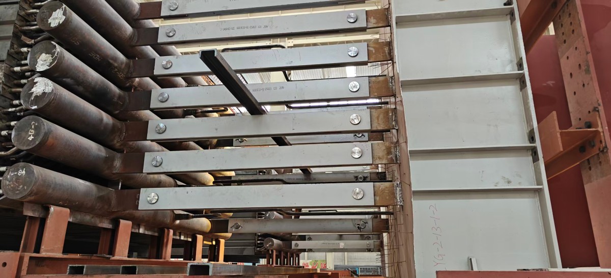
- coordinate module dimensions with transport and erection limits.
Manufacturing engineering
- establish finning procedures for each tube/fin material combination;
- develop serpentine bending parameters;
- prepare pressure-part welding procedures;
- define preheat and PWHT requirements where applicable;
- plan header fabrication and coil assembly;
- provide jigs and dimensional-control methods; and
- define traceability throughout production.
Inspection and documentation
- incoming material verification;
- dimensional inspection;
- fin-weld production control;
- bending inspection;
- pressure-part welding inspection;
- NDE in accordance with Code and project requirements;
- heat-treatment and hardness records where applicable;
- PMI where required;
- pressure testing where applicable; and
- complete manufacturing data records.
This is the practical boundary between a company that can manufacture finned tubes and a company that can supply complete HRSG heating surfaces.
9. Conclusion
HRSG heating-surface design is a coordinated exercise in heat transfer, pressure-drop control, materials engineering and fabrication.
The most reliable approach is not to apply one material or one fin pattern throughout the unit, and not to rely on generic turbine-class rules.
Instead, each heating surface should be developed from the actual project data through a clear engineering chain:
That approach keeps the design technically defensible and, equally important, ensures that what is calculated can actually be manufactured, inspected and delivered.
About Boyu Heavy Industry
Shandong Boyu Heavy Industry Technology Group Co., Ltd. manufactures heat exchangers, pressure vessels, boiler pressure parts and HRSG / waste-heat boiler heating surfaces.
Our relevant manufacturing capabilities include:
- high-frequency welded helical finned tubes;
- solid and serrated fin configurations;
- carbon-steel, alloy-steel and stainless-steel tube / fin combinations;
- serpentine tube coils;
- header-connected heating-surface assemblies;
- modular heating-surface fabrication;
- alloy-steel welding and heat-treatment control;
- dimensional inspection and NDE;
- material identification and manufacturing traceability; and
- project documentation for international supply.
Typical supply scope includes superheaters, reheaters, evaporators, economizers, finned-tube coils, headers and modular heating-surface assemblies for HRSGs and industrial waste-heat boilers.
Applicable certificates, manufacturing qualifications, inspection plans and project references can be provided against the specific project requirements.
Technical enquiries and quotations: boyuheatexchanger.com