

Our News
Find out about our latest news here.
Latest News
- ▶ What Are the Heating Surfaces in a Waste Heat Boiler? Superheater, Evaporator and Economizer Explained
- ▶ Buying Pressure Vessels from China: How to Read a Q345R and an SA-516 Gr.70 Mill Certificate
- ▶ Boyu Heavy Industry Adds Power Engineering Construction License to Its ASME-Certified Manufacturing Base
- ▶ Inside the Shop: What Those Chalk Marks on a Vessel Mean
- ▶ Gas Turbine HRSG Heating Surfaces: Design, Materials, Finned Tubes and Manufacturing
- ▶ Waste Heat Boilers Explained: Complete Units vs. Heating Surface Modules
Message
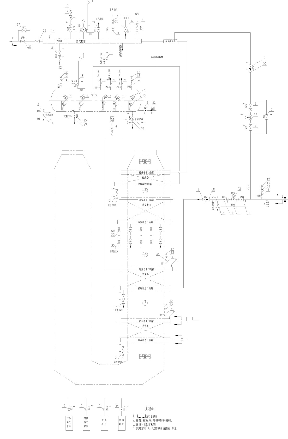
A waste heat boiler is often thought of as a boiler, but it behaves much more like a large heat exchanger. It burns no fuel of its own. All of its heat comes from the hot gas leaving an upstream process — a converter, a coke dry quenching plant, a glass furnace, a sulphuric acid plant, a gas turbine exhaust, a hazardous waste incinerator. Its job is to take as much heat as possible out of that gas stream before it reaches the stack, and put it into water and steam.
The reason this job is split across several banks of heating surface, rather than done in one large exchanger, is that both the gas temperature and the state of the water change continuously along the way. Once you see that, the arrangement of the heating surfaces no longer has to be memorised — it can be derived.
1. Why the Heating Surfaces Are Arranged in Stages
Gas temperature falls steadily from inlet to outlet. It may enter at 900 °C and leave at 150 °C. Over that same path, the water side passes through three quite different states: subcooled water, a boiling steam-water mixture at saturation temperature, and finally superheated steam.
Two differences matter.
Temperature level. At 1.6 MPa, saturation temperature is roughly 201 °C. Feedwater may enter at 60 °C, while superheated steam has to leave above 300 °C. The coldest fluid on the water side is the feedwater; the hottest is the superheated steam.
Heat transfer capability. When the tube contains a boiling steam-water mixture, the inside heat transfer coefficient is very high. Tube metal temperature is effectively held close to saturation temperature. When the tube contains dry steam, the steam is far less effective at carrying heat away, and for the same gas temperature the metal will run significantly hotter than the fluid inside it.
Put those together and the arrangement follows. The superheater must sit in the hottest gas, because only a large temperature difference will raise steam to the required superheat — but for exactly the same reason it is the least well cooled component in the boiler, and therefore the one that demands the best materials and the most careful metal temperature calculation. The evaporator sits in the intermediate zone, where boiling heat transfer protects the tubes and allows relatively high gas temperatures to be handled safely. The economizer sits in the cold end, where the gas has already given up most of its heat but the feedwater is also cold, so a useful quantity of heat can still be recovered.
Following the gas, the standard order is therefore: superheater → evaporator → economizer, with some units adding a hot water heater or low-pressure economizer at the very tail. The water side runs counter to it: feedwater → economizer → drum → evaporator → drum → superheater → steam outlet.
2. The Superheater
The superheater raises saturated steam leaving the drum above saturation temperature. Why superheat at all? Saturated steam begins to carry moisture as soon as it loses a little heat in the pipework, which is hard on turbine blading and on many downstream processes. Superheat provides a temperature margin during transport, and superheated steam does more work per kilogram.
It is the most demanding component in the boiler:
- High metal temperature. Design metal temperature must be calculated for the worst-case thermal deviation, and material selected on that basis — carbon steel at the low end, then alloy grades such as 12Cr1MoV or 15CrMo, and stainless grades where steam parameters are higher.
- Temperature control. Outlet steam temperature moves with load, so a spray attemperator (desuperheater) is normally fitted, injecting a small quantity of feedwater into the steam. Spray water quantity, atomisation quality and the length of the mixing section downstream all affect how well and how evenly the temperature is controlled.
- Start-up protection. During start-up there is no steam flow yet. If hot gas is already entering, the superheater tubes have nothing cooling them and can overheat rapidly. This is why a vent-to-atmosphere valve is normally fitted at the superheater outlet: it establishes a forced flow through the tubes during start-up. It also explains a requirement that appears on many drawings — that this motorised vent valve must be capable of stopping at intermediate positions, since it is used for continuous modulation rather than simple open/close duty.
A related detail that often prompts questions: where two safety valves are fitted, they are frequently set at different pressures, with the superheater valve set lower than the drum valve. This is deliberate. Lifting the superheater valve first guarantees that steam continues to flow through the superheater tubes during an overpressure event, instead of the relief action itself leaving them dry.
3. The Evaporator
The evaporator is where steam is actually generated, and it is the heart of the boiler.
Together with the drum it forms a closed natural circulation loop. Saturated water in the drum flows down the unheated downcomers to the evaporator lower header. Inside the heated tubes it partly evaporates; the resulting steam-water mixture is less dense and rises through the risers back into the drum. The drum separates steam from water, sends the steam to the superheater, and returns the water to the loop. No pump is involved — the driving force is the density difference between the water in the downcomers and the mixture in the risers.
Two engineering quantities have to be respected:
- Circulation ratio — the mass of water circulated per unit of steam generated, typically in the range of ten to several tens. Too low a ratio means high steam quality inside the tubes, with a risk of departure from nucleate boiling and a sudden rise in metal temperature.
- Circulation reliability — downcomers must be generously sized and unheated, and the piping arranged to avoid steam pockets or stagnant tubes. This calls for a circulation calculation checking individual tubes, not a layout copied from a previous project.
Waste heat boilers have a particular characteristic here: their heat input follows the upstream process. When the process trips or swings, gas flow and gas temperature swing with it and the boiler simply has to cope. Evaporator design and water level control must therefore allow for that. Feedwater control is commonly split into a large valve and a small valve, with the small one taking low-load trim duty.
4. Economizer and Tail-End Surfaces
The economizer sits at the cold end and preheats feedwater with gas that has already been cooled. It is the least conspicuous bank, but its contribution to plant efficiency is direct: lowering stack temperature by roughly 20 °C improves boiler efficiency by about one percentage point.
Its principal risk is not overheating but low-temperature corrosion. If the gas contains sulphur, sulphuric acid vapour will condense on tube surfaces once they fall below the acid dew point, and the resulting dilute acid attacks the metal at a significant rate. In dusty gas, condensation on the tube also makes ash stick, and the deposit grows until passages block. The design constraint is therefore firm: tube metal temperature must stay above the acid dew point of the gas. In practice this is achieved by controlling feedwater inlet temperature — adding a hot water recirculation loop where necessary — or by building the coldest section from corrosion-resistant material such as ND steel, or in severe cases enamelled or fluoropolymer-coated tubes.
Where dust loading is high, the economizer also faces fly ash erosion. Erosion rate varies roughly with the cube of gas velocity, so cold-end gas velocity must be limited and shields fitted on the leading tubes.
Some units add a further hot water heater downstream of the economizer to push stack temperature lower still. The heated water does not return to the drum; it serves deaerator make-up, district heating or process use. The principle is the same as the economizer — this is simply the last step in cascaded heat recovery.
5. The Drum: Not a Heating Surface, but Indispensable
The drum absorbs no heat, but it is the hub of the entire steam-water system and performs three functions:
- Steam-water separation. What arrives from the risers is a mixture. Internals — cyclone separators, baffles, wire mesh — remove the water so that outlet steam meets its moisture specification. Otherwise dissolved salts are carried into the superheater and turbine and deposit there.
- Storage and buffering. The water inventory in the drum absorbs load swings, which matters especially where the gas-side duty is unsteady.
- Water chemistry control. Boiler water concentrates as evaporation proceeds. It is controlled by continuous blowdown, drawn from just below the water surface where salt concentration is highest, and by intermittent blowdown from the lowest point to remove sludge, while phosphate or other chemicals are dosed through a chemical injection connection. The drum also carries the safety valves, bi-colour and electrical contact level gauges with their balance vessels, and the sampling points for feedwater, boiler water and saturated steam.
6. Construction Types
"Evaporator" describes a duty, not a construction. What it is actually built from depends on the gas:
- Bare tube — simplest, lowest surface density, but resists fouling and is easy to clean. The right choice for heavily dust-laden or sticky gas, such as converter gas and many metallurgical furnaces.
- Spiral finned tube — several times the surface area for a given volume, with large savings in size and cost. Suited to clean gas such as gas turbine exhaust or natural gas combustion products. Fins should be used cautiously in dusty gas, since the gap between fins is where ash accumulates.
- Membrane wall — tubes joined by fins welded into a gas-tight panel, acting as both heating surface and enclosure. Used where sealing matters in high-temperature radiant sections.
- Forced circulation — where a compact or horizontal arrangement leaves insufficient natural driving head, a circulating pump can be added, at the cost of rotating equipment and auxiliary power.
Cleaning method has to be selected alongside: steam soot blowing, acoustic cleaning, mechanical rapping or shock-pulse systems, each suited to a particular type of ash.
7. What Actually Limits Heating Surface Life
Field experience concentrates failures into a few categories:
- Fouling and erosion — most common at the cold end, showing up as local wall thinning and tube rupture. Controlling gas velocity and fitting shields at the design stage is far cheaper than retrofitting after commissioning.
- Low-temperature corrosion — the inevitable result of designing metal temperature below the acid dew point, and typically revealed one or two operating seasons in.
- Thermal deviation — uneven heat absorption and flow among parallel tubes, leaving individual tubes overheated. Header design and orifices are what balance it.
- Water chemistry — inadequate feedwater treatment or insufficient blowdown leads to internal scale, degraded heat transfer, rising metal temperature and eventually bulging and rupture. Sampling and dosing systems look like minor details on a drawing; they are not.
- Cyclic stress and fatigue — waste heat boilers start and stop with the process they serve. Tube-to-header fillet welds and nozzle attachments are the usual locations for fatigue cracking.
8. What to Check When Specifying or Buying
From a procurement and manufacturing point of view, a few items are worth insisting on:
- Design code. Domestic Chinese units typically follow the GB/T 16507 series. Export projects are commonly built to ASME Section I (power boilers) or Section VIII (pressure vessels). This must be settled at enquiry stage, because the code governs material, welding, examination and stamping throughout.
- Material selection and metal temperature calculation. Superheater material should be supported by a metal temperature calculation, not by reference to a previous project.
- Circulation calculation. Confirm that the natural circulation loop has been checked tube by tube.
- Welding and NDE. Examination percentage on tube butt welds, surface examination on tube-to-header fillet welds, and the hydrostatic test plan.
- Manufacturing credentials. Class A boiler manufacturing licence and pressure vessel manufacturing licence; for export, an ASME "S" stamp for power boilers or "U" stamp for pressure vessels, plus the corresponding NB authorisation for field assembly where applicable.
Heating surfaces look like nothing more than an arrangement of tubes, but they operate under the harshest temperature and fluid conditions anywhere in the plant. Every choice — position, material, velocity, metal temperature — traces back step by step to the gas temperature profile. Follow that chain and selection, bid evaluation and troubleshooting all become considerably clearer.
PROFESSIONAL CONSULTATION
If you are interested in our products and want to know more details, please leave a message here, we will reply you as soon as we can.